Since its launch on January 18, 2024, *Love and Deep Space*, a surreal 3D immersive dating simulation mobile game, has surpassed 70 million players worldwide and was named Best Mobile Game at Gamescom 2025.
At today’s Unite Shanghai 2025 event, engine engineers from *Love and Deep Space* delivered their first in-depth technical presentation, offering a behind-the-scenes look at the game’s development and revealing how they use a cinematic-quality rendering pipeline and realistic, intricate physics effects to create a truly immersive world for players!
△ The event was packed to capacity
The most popular session at this year's Unity Conference
At DiDi, sharing and creating are an integral part of our daily work. Over the past year, DiDi has hosted nearly 40 internal sessions, with a cumulative total of 5,000 employee participations! Technical sessions accounted for over 50% of these events! Presenters came from various production teams and technical departments, covering practical experiences and cutting-edge explorations across different fields. Thanks to an open atmosphere of exchange, expertise and ideas flow freely, sparking abundant inspiration!
Below is a recap of the full content of the "Love and the Deep Space" technical session:
The presentation on the rendering framework for *Love and the Deep Sky* primarily covers three areas: [scene rendering optimization, lighting solutions and pipeline design, and shadow optimization]. During development, we made extensive modifications to the engine source code based on Unity 2019 and developed a custom SRP pipeline. The current live Android version uses GLES 3.1, and a Vulkan version will be released in the future to continuously improve performance and meet players’ expectations for high-quality gaming experiences.
1. Scene rendering optimization
As part of our scene rendering optimization efforts, we developed a scene rendering system called 【RendererGroupRenderer】, in which each rendering batch is referred to as a RenderGroup. Through this system, we have implemented the following features:
- Custom static scene description: We have removed GameObjects to avoid the performance overhead associated with updating a large number of them.
- Optimizing CPU-to-GPU upload frequency: This primarily involves the upload of InstanceData and ConstantBuffers. Regarding InstanceData upload optimization, in the early stages of the project, for small-scale indoor scenes, we used statically generated InstanceDataBuffers combined with BVH-based clipping. As the project progressed and scene fidelity requirements increased, we later shifted to performing clipping and instance filling on the GPU.Optimization of ConstantBuffer uploads will be detailed in the subsequent section on "Single Draw Call Performance Optimization."
- CPU-Side Burst+Job System Parallel Coarse-Cutting: For static objects, we have implemented a highly concurrent cutting system using the Burst+Job System. Coarse-cutting is performed exclusively on the CPU side, while fine-grained cutting tasks are delegated to the GPU.
InstanceData Data Format
The use of InstanceData in the form of Constant Buffers, which is common in the industry, has some drawbacks, such as a 64KB size limit, a small constant buffer, and a tendency for cache misses to occur during dynamic indexing, leading to performance degradation.Another common approach is to pass InstanceData via SSBO, but this method typically offers poorer read performance than a ConstantBuffer when the cache is not hit. Additionally, some Android devices do not support reading SSBO in vertex shaders under GLES, which limits its compatibility. Furthermore, both of these solutions share a common issue: they rely on dynamic indexing, which is not performance-friendly on low-end mobile devices.
To address these issues, we propose a solution that amounts to “old wine in a new bottle”—Vertex Stream-based Instance Data.
- 使用PerInstance Step的Vertex Stream作为Instance Buffer;
- Uses the Vertex Fetch cache, requires no dynamic indexes, has a high cache hit rate, and has no compatibility issues;
- Output to the instance vertex buffer via ComputeShader to enable GPU-driven rendering.
Using the Vertex Stream from the PerInstance Step as the Instance Buffer—this is an instancing method that has been supported since the inception of GPU instancing. It avoids both the performance issues associated with dynamic indexing and the compatibility issues with SSBO. We can also achieve GPU-driven instancing with high GLES backward compatibility by outputting to the Instance Vertex Buffer via a Compute Shader.
Finally, since the Unity engine does not natively support PerInstance Step vertex streams, we customized the engine accordingly. Ultimately, we exposed a `DrawMeshInstancedTraditional` interface within the CommandBuffer to the upper layers, which requires another mesh to be passed in as instance data. We also added corresponding interfaces to configure the vertex semantics for each data segment within the instance mesh.
GPU Driven
We pre-allocate the IndirectParameter Buffer and the Instance Data Buffer based on the number of groups and instances (note that the Instance Data Buffer is only pre-allocated; the actual data is populated during GPU culling).
At the same time, we pre-calculate the instance offset for each group and store it in the `InstanceStart` field of the parameter, binding only a single instance buffer throughout the entire process.
In addition, we need to generate an object-specific information buffer (containing GroupID, LOD distance range, bounds, transform, and other information) to retrieve the properties of each object during GPU clipping.
- CPU Pruning: Before performing GPU pruning, we first execute a CPU coarse pruning to determine whether the entire Group is visible. Starting from a root bounding box, we compare the ratio of the total volume of the object bounding boxes to the volume of the merged bounding box; if this ratio falls below a threshold, we recursively split the bounding box (the primary goal being to prevent the generation of an oversized bounding box caused by two objects being too far apart).We also use PVS to further assess the group’s visibility. Since we lack a feature equivalent to DX12’s IndirectExecute, our GPU pruning can only reduce the number of instances—it cannot eliminate the group’s draw calls entirely. Therefore, CPU pruning is necessary to accurately eliminate groups that are completely invisible.
- GPU Clipping: GPU clipping performs per-object 3-stage clipping on all groups in a single dispatch, including frustum clipping, LOD clipping, and Hiz occlusion culling. After clipping, the `InstanceCount` parameter is incremented by 1, and `InstanceData` is output.
- Shadow Culling: Following the method shared by Dragon's Dogma, we reproject the scene's depth into shadow space to create a Shadow Culling Mask. If the volume cast by the Shadow Caster does not intersect with the mask, we can cull it to avoid rendering unnecessary shadows.
Additionally, regarding the section titled “Why We Did Not Implement Cluster/Meshlet,” first, there is significant underlying overhead on mobile devices, and second, implementing Cluster under GLES also presents compatibility issues. After careful consideration, we believe that prioritizing the optimization of single DrawCall performance will yield a more immediate and tangible performance boost.
Single Draw Call Performance Optimization
In our past observations, we have found that many optimizations aimed at reducing CPU rendering time tend to focus too much on the number of draw calls, while neglecting the execution time of each individual draw call. We believe that reducing the number of draw calls is merely one optimization technique; ultimately, CPU execution time is the only metric that matters.
Modern mobile devices and graphics standards have long been capable of handling a large number of draw calls. The HypeHype engine team discussed this at SIGGRAPH 2023—they tested 10,000 draw calls with different meshes and materials on an iPhone 6s, which took only 11.27 milliseconds.Other comparable Android devices can generally maintain frame rates above 60 FPS as well. Back in 2014, when Metal was first introduced, it was touted as capable of handling 10 times more draw calls than GLES.
Eleven years later, the reason we still struggle with excessive draw calls stems primarily from various overheads, including frequent PSO switching, buffer submissions and copies, engine rendering logic, and excessive RHI interface calls—all of which increase the CPU load. Therefore, we believe that performance optimization should not focus solely on the number of draw calls, but rather take all these factors into account.
- PSO Switching Optimization: This primarily depends on the trade-off between the number of shader variants and shader complexity for each project. The RenderGroup rendering queue sorts items based on the priority of shaders, materials, and meshes. Additionally, we apply special handling to shadows: materials without AlphaTest are rendered using the same shader for Shadow Depth, thereby reducing the frequency of PSO switching during shadow rendering.
- Buffer Submission Optimization: Under GLES, mapping and unmapping buffers incurs significant overhead. While persistent mapping supported by modern RHI can significantly reduce upload time, it still cannot eliminate the multiple copies of data from the main thread to the render thread and then to buffer memory, as well as the memcmp operations. Therefore, we adopted the following three targeted strategies to significantly reduce buffer upload:
- PerRendererBuffer stores parameters specific to each Renderer (such as the ambient light SH received by an object) in a Uniform Buffer maintained by the Renderer object, which is directly bound during rendering;
- PerShaderBuffer is designed for uniform buffers that do not need to change on a per-material basis; it is submitted only once when the shader is switched. Compared to PerRendererBuffer, PerShaderBuffer is more flexible and can support different shader variants;
- For PerMaterialBuffer, we leveraged the SRP Batcher code to pre-generate per-material buffers and bind them directly.
- Rendering Logic Optimization: To ensure flexibility and stability, commercial game engines perform complex logical checks during rendering. For example, within the Unity engine, every call to `Draw` first invokes an `ApplyMaterial` function, which updates all rendering states and parameters before rendering. When there are a large number of draw calls, this can result in significant overhead. Therefore, we have implemented the following optimizations:
- The `ApplyMaterial` interface has been separated into a standalone component and is only actively called by the upper layer when a material or parameter needs to be switched;
- When changing PerMaterialBuffer, simply use the simplified dedicated interface.
After optimization, our CPU reduced the execution time by one-third for the same number of draw calls.
- RHI Call Optimization: The primary goal of RHI call optimization is to reduce graphics API calls other than `Draw Primitive`. Specific optimizations include:
- Merge Vertex and Index Buffers with the same stride to avoid binding VB/IB for each draw call, reducing execution time by 15%;
- When the resource remains unchanged, skipping the DescriptorSet setup reduces execution time by an additional 30%; however, when SetDescriptors itself is time-consuming, and switching descriptors also increases the execution time of the next draw, as described in Arm’s Best Practice Guide.
We tested the rendering time for 5,000 draw calls on low-end Android devices. When using the engine’s native rendering, the rendering thread took 34.79 ms.After optimizing the buffer submission and rendering logic, the time dropped to 22.97 ms. Following further optimization of the number of RHI calls, the time decreased significantly to 11.8 ms. Ultimately, while keeping the number of DrawCalls constant, we reduced CPU time to less than one-third of the original value.
Results of Benchmark Scenario Tests for Other Optimization Attempts
We also tested some new RHI features, including:
- Multi-Draw Indirect (MDI): This feature delivers significant performance gains on supported devices and helps mitigate the issue where GPU occlusion culling may result in empty draw calls (reducing the number of draw calls submitted by the CPU);
- Bindless: However, Bindless’s performance has been less than ideal, with mysterious performance regressions even on the latest Android devices. By combining MDI with Bindless, we can render nearly all objects with a single draw call, but CPU usage is actually higher than when not batching. This serves as a cautionary tale against an excessive focus on the number of draw calls.Of course, we hope that future mobile chips will offer better support for Bindless. For now, we have developed an alternative system—a Feedback-free SVT system based on Unity Texture Streaming—which is still in the validation phase.
Based on the results of the benchmark tests, compared to the original rendering without instancing, RenderGroupRenderer reduced draw calls by one-third, cut rendering thread execution time by three-quarters, and reduced main thread execution time by two-thirds (although C# execution time increased, the reduction in time spent on native engine clipping and GameObject updates still resulted in significant overall optimization).
2. Lighting Plan
Lighting Plan
- Front-facing rendering pipeline:
We chose to use the forward rendering pipeline for this project based on several considerations. First, the forward pipeline has distinct advantages when it comes to handling complex and ever-changing artistic requirements; we do not need to worry about whether adding certain material properties will cause the G-buffer to bloat.
Second, traditional deferred pipelines are not very bandwidth-efficient on mobile platforms. OnePassDeferred, however, has some limitations in terms of flexibility; for example, it cannot change the resolution of the render pass midway through, nor can it fetch pixel data beyond the current position.
Under GLES, there are also compatibility issues with FrameBufferFetch. Different chips support varying numbers of RTs; some support only one RT, requiring a switch to PLS implementation. However, our tests show that PLS performance is not ideal.
Additionally, the engine’s built-in per-object 4-light system isn’t sufficient for larger objects, so we tried Forward+. However, Forward+ is too computationally intensive on older devices. If we limit the maximum number of lights per tile, the number of lights within a tile becomes unpredictable when the camera moves, and exceeding the limit can cause rendering bugs.
To address these issues, we implemented a horizontal world space tile division—with a default grid size of 2 meters—spanning the area in front of the camera. Each tile contains up to four light sources and a 128×128 index map. This division ensures consistent light source overlap across tiles, making it easier to identify any overshoot issues during production.
- Improvements to the Vulkan version pipeline
We have added a Subpass-based Light Pre-Pass to the pipeline for future versions of Vulkan.
In the Pre-Z Pass, we output a simplified GBuffer RT and store it.Since our local lighting uses a simplified PBR model without Fresnel effects, we do not need to output specular or albedo data to the G-buffer. Instead, we pack normal, roughness, and some specific material IDs or attribute information into an RGBA8 G-buffer. We can then run a lighting volume rendering pipeline similar to deferred shading, saving the geometric lighting results to tile memory.
Next, in the Shading Pass, we will redraw the object and retrieve this lighting information, then combine it with material properties such as albedo obtained during rendering to produce the final lighting result.
We encode the MotionVector required by TAA as RGBA8, where R + G == 0 indicates no valid velocity; this allows certain materials that do not output velocity to store other information in the BA channel.
For example, when dealing with simple, high-volume vegetation, we store their UV information in the BA channel of the MotionVector. This way, during the shading pass, we only need to perform post-processing to retrieve the geometric data from the gbuffer and the UV information from the MotionVector to restore the vegetation’s material appearance.
The pipeline flow for the Vulkan version is roughly as follows: First, the PreZ Pass outputs depth, the GBuffer, and motion vectors; then, shadow occlusion culling is performed; next, shadow depth rendering is executed; followed by calculations such as ambient occlusion (AO) and screen-space SSS; then we enter the NativeRenderPass, where the SubPass calculates the shadow mask, performs the light pre-pass, and executes the normal shading pass.Finally, the RenderPass exits, and other post-processing passes are executed.
Improvements to the Vulkan version pipeline also have certain limitations; for example, the Light Pre-Pass can only replace the default lighting model. For lighting models that require additional G-buffer channels, the Forward+ pipeline must still be used.
However, we provide a per-light source option that allows you to force the use of the Standard Lit Model for a specific light source, applying it uniformly to all materials. This allows pixels within the same tile to be affected by more than four lights, albeit at the expense of lighting model accuracy.
- Good morning
For the diffuse GI component, we adopted a relatively traditional Lightmap+Light Probe approach. The Lightmap stores only indirect lighting information. In addition to the standard single-sampling-point-per-object mode, our Light Probe also offers a multi-sampling-point mode that allows multiple sampling points to be set for each object, with interpolation based on the center-of-mass coordinates of line segments, triangles, or tetrahedrons.
In the two comparison images below, the left image shows the result using a single sampling point, with uniform ambient lighting at the bottom of the box; the right image shows the result using two sampling points, revealing that the left and right sides are illuminated by different indirect light sources.
For Specular GI, we primarily use Reflection Probes with AABB correction. Additionally, for certain types of floors or water surfaces, we also use planar reflection proxies. These can generally be viewed as a form of HLOD specifically designed for rendering reflections.
In addition, we followed the approach used in God of War and normalized the Reflection Probe's CubeMap.Specifically, we generate an ambient light SH coefficient based on each pixel in the CubeMap, then divide the pixel color by the ambient light in that direction to obtain a normalized CubeMap. During actual rendering, we multiply each pixel by the actual ambient light it receives in the reflection direction to reconstruct the reflected color.
The advantage of this approach is that even when a large number of objects sample the same reflection probe, reflections from different areas can still produce distinct variations in brightness.
3. Shadow Optimization
Functional Design
The basic design of our shading system is as follows:
- Level 3 CSM+ Character Close-up Shadows / Multi-Character POSM: Level 3 Cascade CSM combined with Level 1 character-specific close-up shadows; POSM (Per-Object Shadow Map) is used in certain multi-character scenes;
- Supports projection from two spotlights;
- ScreenSpaceShadowMask: The results of the above shadow calculations are all output to an RGBA8 ScreenSpaceShadowMask;
- R: Directional Shadow, G: Local Shadow 1, B: Local Shadow 2, A: AO: The R channel stores the main light shadows, the G and B channels store the spot light shadows, and the A channel stores the AO information.
Distance to exclusion
First, we performed a simple distance culling: we adjusted the depth values of the triangle vertices in the ScreenSpaceShadow post-processing based on the shadow distance, and then rendered using ZTest Greater to eliminate shadow calculations beyond the shadow distance.
Since we need to sample the depth buffer when calculating shadows, we require two copies of the depth buffer—one for testing and one for sampling. In the NativeRenderPass, we will copy a memoryless depth buffer for testing to minimize additional read and write bandwidth.
Penumbra Detection
We have added a penumbra detection feature. First, we compute the PCF at 1/4 resolution, then sample a 1/4 mask in the full-resolution shadow pass, applying the full-resolution PCF only to pixels whose shadow values fall within the intermediate range. This approach reduces computational load while maintaining the desired visual quality.
To avoid issues with inaccurate pixel detection in certain details after doing this, we calculate two sets of normals: one based on the gradient of the position in the 1/4 buffer, and the other based on the four depth values from the full-resolution gather. If the angle between the normals exceeds a threshold, the low-resolution pixel is deemed unreliable, and full-resolution PCF is enforced.
The following is the Debug view of the scene. We have identified the red areas as penumbra regions; only these pixels will undergo full-resolution PCF.
Pixel-by-pixel bias
We implemented per-pixel shadow bias using the Receiver Plane Depth Bias algorithm. The principle behind it is relatively straightforward: first, we apply the two-dimensional chain rule to the partial derivatives of the shadow coordinates in screen space to compute the partial derivatives in shadow space.
Using the partial derivative and the PCF sampling offset, we can calculate the bias value. For the center point, we use the bias result with a 1-pixel offset as the initial bias.
The figure below shows a comparison between fixed bias and per-pixel bias:
In the image on the left, which uses a fixed bias value, you can see a region of light leakage at the bottom of the box, as well as some self-shadowing artifacts on surfaces that are nearly perpendicular to the direction of illumination. After applying a per-pixel bias (right image), we only increase the bias in areas with higher gradient values, which resolves the self-shadowing artifacts while preserving the projection details.
However, when there are discontinuities in the screen depth, the per-pixel bias may produce incorrect results, leading to some light leakage. To address this issue, the artist must manually specify the minimum and maximum ranges for the bias.
Scrolling Cached Shadow Map
For scenarios with a high number of draw calls, we also experimented with Scrolling Cached Shadow Maps, specifically:
- Cache the CSM depth; for objects that are fully enclosed by the shadow volume in both the previous and current frames, simply project the CSM from the previous frame onto the current frame’s projection position to obtain the shadow depth, thereby avoiding the need to render the object directly;
- Scrolling is applied only to the final level of the cascade; when the cascade scope is small, a large number of objects will intersect with the frustum, limiting the optimization effect;
- Update the cache at intervals of several frames to reduce the load on the bandwidth.
In the future, we plan to add support for Local ShadowMap Atlas and caching mechanisms. We will support the projection of more than two local lights and dynamically adjust the ShadowDepth resolution based on the light source’s screen coverage. We will also introduce static caching support for distant local light sources.
1. Character Lighting Scheme
When working with character lighting setups, I’m sure most of you have encountered the following types of issues at one time or another:
Breaking these issues down, we can summarize them into the following three requirements:
Based on the above requirements, we developed a specific lighting design for the characters.
Lighting consists of 【direct light】 and 【indirect light】. Generally, we only have one parallel light source—which we commonly refer to as the main light. The main light illuminates the scene normally, but when lighting characters, we retain its direction and use a method similar to a post-process box to override the main light’s color and brightness. The specific implementation is as follows:
- Pass an additional copy of the character's main light color to the shader; when the character's shader retrieves the main light, it will use this color;
- Provides the character with an additional non-projecting parallel light source to serve as a contour light;
- Two additional lights have been reserved for the character. These additional lights can be any combination of spotlights and floodlights, and they can properly illuminate the character and scene objects within their range (since a 2-meter grid can accommodate up to four additional lights, two lights have been allocated to the character).
For indirect lighting, we use Unity’s LightProbe system to create probes. We implemented the functionality for saving indirect lighting data to the probes ourselves, and we maintain two separate sets of probes—one for the scene and one for the characters—which are stored and used independently;
We use the same reflection probe for ambient light highlights, but for certain special materials, we provide the option to apply a CubeMap to the material to override the ambient reflection probe.
We store the lighting information affecting these characters in a ScriptableObject, which the lighting artist can adjust and then save as a template. The image on the bottom right shows the information saved in the character lighting setup, including the two parallel lights and two additional lights mentioned above, as well as the shaders saved by the probes, along with additional adjustment options in the post-processing boxes and whether to use custom reflection probes.
Finally, we use a manager to manage them using a stack-like approach. The choice of a stack-based management method is closely tied to the specific use case—typically, aside from loading new lighting schemes, the most frequently used feature is restoring the previous lighting scheme, which is why we adopted this stack-based approach.
At this point, the solution already includes features such as separate characters and scenes, real-time switching, and support for custom save templates. Finally, we defined the lighting scheme switch as an event behavior in the story editor, enabling seamless lighting animations.
The interlocking light effects are shown below:
The image below shows the project's dedicated scene editor. Virtually all lighting and shadow parameters, as well as some post-processing and physics effects, can be controlled within this scene editor.
2. Close-up of shadows
Light and shadow have always been inseparable.As mentioned earlier, our shadow solution consists of a three-level CSM combined with close-up shadows. The implementation uses a designated bone on the character as the center of a sphere with a specified radius. This sphere is used to construct and generate the shadow map. During screen-space shading, a precision comparison is performed, and the higher-precision map—either this shadow map or the one from the cascaded shadows—is selected as the shadow map for that pixel.
As shown in the following animated image, the character was originally entirely within the main light’s shadow. When the close-up shadow is enabled, the character becomes normally lit by the main light—this is because the close-up shadow modifies the near clipping plane. In other words, our close-up shadow is a separate, adjustable shadow map with specific parameters, including near and far clipping planes, maximum distance, the light source used, and the often-troublesome bias.
3. Skin Details
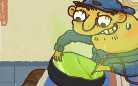
When it comes to the skin, we’ll focus on some specific details, using the blushing and sweating effects as examples.
- Blush effect
Generally speaking, the process of blushing is a gradual one, with different areas of the face turning red to varying degrees. For example, when most people blush, it usually starts with the ears, then spreads to the cheeks, though occasionally the entire face may turn red.
To simulate this process, we took the following steps to make the visuals more vivid and realistic:
- Hand-drawn masks: Use mask textures to control the areas of blush, color gradients, and intensity;
- Multi-channel independence: Allows for separate adjustment of the red tint effect in different areas such as the face, ears, and nose;
- Pre-stored transition process: The transition process of blushing is recorded channel-by-channel on the corresponding curves to achieve natural emotional expression.
- Sweat effect
Our game features a workout companion function, where the male protagonist accompanies players during their workouts; therefore, we need to include corresponding sweat effects. This is primarily achieved through the following three aspects:
- Combining materials and particles: The material shader simulates the skin’s surface sheen and moisture, and the sweat droplet effect offers a choice between a material-based implementation and a VFX-based implementation;
- Control sweat areas with a mask: Use a mask image to define the areas where the material sweats, enhancing the realism and artistic quality of the sweat effect;
- Automated Data Transfer: Changes to master parameters automatically update material and particle parameters.
The figure below illustrates some specific calculation methods and the final results.
△ Calculate the location of sweat droplets and adjust the roughness of their positions
△ Generate random numbers using UV grid IDs
△Simulating the trajectory of falling sweat droplets
△ Sweat-inducing effects of the workout companion system
The presentation on physics effects will focus on four main areas: cloth simulation implementation, real-time performance control, development using Unity DOTS, and the collision detection module.
1. Fabric simulation implementation
To address some specific issues in the project, we developed an in-house fabric simulation system.
Skeleton-Based Cloth Simulation System: StrayCloth
StrayCloth employs a simulation method that combines XPBD with sub-steps. Compared to PBD, XPBD has the advantage of being independent of the number of iterations and time step size; when combined with sub-steps, it can significantly improve the convergence of the solution.
What makes this approach unique is that we use skeletons as simulation particles, meaning that each particle carries rotation information in addition to its position.
In the actual implementation of the substeps, we use dynamic substep durations ranging from 1/200 to 1/300 to accommodate different performance-intensive scenarios. Additionally, we perform motion interpolation on moving objects within the scene, which results in more stable collision effects. In fact, while motion interpolation does not impose a significant performance overhead, it is still quite cumbersome to implement in practice due to the wide variety of object types, such as static particles, colliders, and wind fields.
Why use a skeleton instead of a proxy mesh? Mainly for the following three reasons:
- "Love and Deep Space" has complex performance requirements in terms of storytelling, combat, and costume changes; a skeletal animation system can effectively handle the transitions and calculations;
- Given the need for controllability and the performance limitations of mobile devices, the skeletal animation approach offers artists greater creative freedom;
- By using bones and constraints, you can build mesh-like structures to achieve a similar effect.
Skeletal Constraint Scheme
In existing skeletal cloth simulation solutions, skeletal constraints are typically implemented using local and global shape constraints. While this approach is simple and fast, it has a significant drawback: when used for cloth simulation, the results tend to have a cartoonish style, which does not align with the realistic 3D aesthetic pursued by *Love and Deep Space*;Furthermore, parameter adjustments are not intuitive, as the system relies on two separate bending strength parameters—global and local—which makes it difficult for artists to fine-tune the results and ensures consistency across different scenes.
Therefore, for the skeletal constraint scheme, we selected the Cosserat Rod-based skeletal constraint. Its advantages include:
- The result looks more natural and aligns with the overall realistic art style of *Love and Deep Space*
- Parameter adjustments are more intuitive, and the strengths of the three axes are independent. In certain scenarios—such as when simulating a skirt—anisotropic bending strengths can be used to approximate the effect of a petticoat.
- Since hair simulation can be reused directly, we can use the same set of constraints for both hair and clothing.
For a concrete example, take a look at the performance of the latest daily card:
Connecting Fabric to Characters
Fabrics and characters are connected primarily in two ways:
- Hierarchy: Static skeletons are directly affected by the character's skeletal animation and move according to the hierarchy.
- This method is relatively simple and works well for joints that tend to be rigid. However, in more complex areas where multiple bones intersect or where there is significant stretching and contraction—such as the elbows, shoulders, and waist—the fabric and the character model are prone to becoming detached.
- Adhesion: Static particles are controlled by the anchor triangles of the character model. The mesh is baked in parallel and updated every frame based on the center-of-mass coordinates.
For special cases where the triangle is degenerate, we use the transformations of the skin bones at the triangle vertices to perform weighted averaging and update the transform of the static particles.
Collision Solution
For the collision system, we use a dynamic BVH to manage the broad phase of scene collisions, with each character represented as a subtree containing its internal colliders as subtree nodes.
At the same time, we use three criteria—role ID, sharing visibility, and component type—to manage the sharing of collision rules across different roles and components.
During the narrow phase, we do not generate contacts directly; instead, we cache collision pairs and resolve them in detail during the substep. Because of the advantages of the substep approach we use, in most cases, simply using DCD is sufficient to avoid penetration issues caused by high-speed motion, eliminating the need to introduce operations such as CCD or predictive contact.
- Implementation of Mesh Collider
For parametric geometric colliders—such as planes, capsules, and boxes—it is relatively straightforward to handle collisions between them and particles or edges. However, in complex areas like the shoulders, neck, chest, and back, parametric geometries struggle to accurately capture the character model’s shape, which can lead to clipping issues. Therefore, we make extensive use of mesh colliders in these areas.
However, since mesh colliders are irregular concave shapes and may sometimes be non-closed, achieving precise collision detection is more challenging compared to parametric geometries, especially on mobile devices. Therefore, we use a hash table as a coarse-grained method for triangle lookup. By combining this with cached results for neighboring triangles, we generate a set of particle-triangle collision pairs before the iteration begins.In subsequent iterations, we determine whether a particle is within the triangle’s bounds. If it is outside the triangle’s bounds, we perform a limited-step triangle search based on the model’s triangle adjacency relationships to obtain the nearest triangle, and cache the result for use in the next iteration.
The GIF below shows some specific examples of how the project performs; as you can see, the performance is quite stable.
Face Collider
A facial collider can be viewed as a specialized type of Mesh Collider. Compared to a basic Mesh Collider, it has a more fixed and smoother shape, with virtually no overlapping triangles originating from the center of the model. Therefore, we use a 16×16 CubeMap to pre-compute the triangles in all directions, allowing us to quickly locate adjacent triangles during collision calculations.
Interlayer collision
Cloth self-collision simulation is the most challenging aspect of the game. For performance reasons, we propose the following solution:
- Using spatial hashing as a lookup acceleration structure
- Pre-stratified by graphics, considering only particle-to-triangle collisions between layers
- To prevent particles from getting stuck between layers, only calculate collisions in the direction of the particle's and triangle's normal vectors
The graphics engine pre-processes the fabric into layers, simulating collisions only between these layers. A hash table is used as a lookup structure to speed up the process. To prevent the fabric from getting stuck between layers, we only consider collisions along the normal vector; if penetration has already occurred, we skip it and leave the correction to subsequent steps.
In practice, we use the particle positions from the previous substep to perform collision detection with the current particle positions; this allows us to easily decouple the data and avoid dependencies.
Interlayer penetration separation
For areas where layer collisions have already penetrated, we drew inspiration from the untangling of cloth and implemented a lightweight solution. By dividing the cloth into layers and starting from the cloth’s anchor points, we calculate the intersections of edges and triangles across different layers. Since our asset structure is necessarily a uniform mesh, we can relatively easily infer the triangles of other particles by comparing mesh vertices.Finally, we resolve the penetration by applying spring constraints to the penetrating particle-triangle pairs. In practice, due to the substep mechanism, the probability of penetration is relatively low; therefore, we employ a frame-by-frame, block-by-block execution strategy to mitigate performance pressure.
2. Real-time performance control
Most of the physics effects in *Love and the Deep* are controlled and adjusted through cutscenes. Our tools team has developed and maintained a very powerful cutscene engine, and building on their work, we have created various function tracks to fine-tune these physics effects.
Here is an example of a Cutscene Physics Track in our game engine. Since our art team pays very close attention to visual details, you can see that the configuration of the physics track is quite complex.
△Cutscene Physcs Track 示例
SmoothBlendPose Track
A very common issue in performance is the physical jerkiness caused by abrupt transitions between movements, which frequently occurs during both narrative scenes and costume changes.
We have developed a fairly general-purpose method that records the initial physical pose and performs pose interpolation between the initial and current poses during transitions. This significantly reduces jitter. Of course, this introduces some computational overhead—typically around several tens of milliseconds—which is generally acceptable in most cases. We provide parameters such as the number of interpolation steps and the step size, allowing artists to adjust these settings according to their specific needs.
Pose Track
Of course, SmoothBlendPose has its limitations and cannot guarantee completely smooth transitions, especially during complex cuts in narrative sequences. We also offer a more straightforward solution: saving the physical state of a specific frame offline and applying that saved state directly to the cloth during playback. This approach completely avoids the issues caused by scene cuts.
Edit Param Track
It is difficult for a single physical asset to accommodate the diverse requirements of various scenes within a story; for example, sometimes you might want the fabric to be softer or stiffer, or the damping to be stronger or weaker.We provide parameter editing tracks that allow you to modify parameters in real time. Most parameters can be overridden, making it very convenient to make adjustments for a short sequence of frames. These parameter adjustments can also be used to create special effects, such as the breaking effect in animations achieved by editing constraint parameters.
Animation Track
Physical effects alone are not sufficient to support every aspect of the scene; in many cases, a combination of animation and physics is required to create interactions.We use animation tracks to bridge and integrate animation and physics, allowing for precise control over the behavior across different time frames. In the actual production workflow, there can be significant differences between how movements appear in the DCC software and how they play out in the engine. This includes situations where, after modifications to the engine’s real-time rigging system, animations may overlap with other elements. Therefore, on top of animation blending, we can overlay physics-based collision effects to prevent such overlaps.
The GIF demonstrates the interaction between the necklace's physics and animation, including transitions from physics to animation and between different animations.
Collider Track & Wind Track
Collider Track and Wind Track allow you to dynamically create and destroy colliders and wind fields within cutscenes. You can flexibly adjust the state of colliders and wind fields to suit different visual requirements. By grouping characters, component types, and fabric layers, you can precisely control the scope of objects affected.
In addition, most parameters for collision bodies and wind field trajectories can be controlled via animation frames, including the shape and size of collision bodies, as well as the direction, range, intensity, and turbulence of wind fields. This allows artists to fine-tune physical effects and precisely control changes.
The GIF shows some examples of the track capsule and the wind field.
3. Development based on Unity DOTS
Jobs + Burst + Mathematics
DOTS is a very powerful toolkit that enables high-performance multithreaded development directly at the C# level. Our physics system is built entirely on the C# layer using DOTS, which makes feature iterations and debugging very convenient. Currently, we can support simulations of over 2,000 skeletal particles.
Of course, we’ve also implemented some targeted optimizations in the project to further improve performance.
Hide Job
In the simulation, the number of jobs and their dependencies are fixed, and job data does not change frequently. Within a frame, a set of jobs with the same number and dependencies typically executes in multiple cycles. Unity Jobs must recreate a job each time a task is initiated; although this can be mitigated by scheduling tasks in advance, it still blocks the main thread. Furthermore, the job must be cleared after execution is complete.Based on these observations, we developed a "Cache Job" solution that pre-creates job data and reuses it during each execution, thereby avoiding the performance overhead associated with recreating jobs each time.
The implementation is relatively straightforward, as it is a dedicated structure designed for specific use cases. An Atomic Queue has been added to store cache jobs, and a fetch-and-add array is used to store the actual jobs. The diagram on the right illustrates the workflow for workers executing cache jobs.
Neon Intrinsics
Burst generates high-performance SIMD code tailored for different platforms, which can be easily viewed in Burst Inspector. After reviewing Burst Inspector and conducting tests on actual devices, it is also possible to further improve performance in certain scenarios by manually writing ARM Neon intrinsics.
Here is an example of how to implement a function that checks whether a vector contains any non-zero elements.
Dot(float4)
I have listed three methods for dot products here. In our test cases, using NEON intrinsics yields a performance improvement of approximately 30% compared to the `mathematics` library. If the target device supports ARMv8.2, you can use the new reduced addition instructions to further boost performance. Generally speaking, most popular devices currently on the market support ARMv8.2.
Transpose(float4x4)
When it comes to transpose operations, we can see that the assembly code generated by the mathematics library appears to have very poor performance; however, by writing the NEON intrinsics manually, we can achieve a significant performance boost.
If you simply need to transpose the data, you can use interleaved reading directly. I’ve implemented it this way here because, in my typical use cases, I transpose four `float4` values to convert a dot product into a vector product.
These are just some of the more common examples from these two projects. Since mathematics code is typically inlined, specific optimizations must be performed based on the code’s context. You can conduct detailed performance testing using Burst Inspector and real-device testing.
4. Collision Detection Module
Why start from scratch instead of using Unity’s established physics engine?
Unity itself includes a mature set of physics modules based on PhysX. The decision to develop a new physics system independent of Unity’s established modules was primarily based on the following considerations:
- "Love and the Deep" features a wide variety of gameplay modes, and the layer settings for each mode are relatively independent; we would very much like to maintain a separate set of layer settings for each one.
- We would like to ensure that certain modules—such as combat—have built-in support for specialized trigger and exit mechanisms, and we also want more flexible control over the execution flow.
- Finally, we also have some ideas regarding performance optimization: specifically, can we use DOTS to improve performance in scenarios where only collision detection is required?
The implementation in *Love and the Deep Space* includes:
- It has essentially implemented all native collision detection features
- Custom Update and Trigger Logic
- A thread-safe query interface that upper-level components can call without any concerns
- Combined with DOTS' lightweight implementation, performance tests show a maximum improvement of approximately 15%.
Example of the Inquiry Process
Since the actual number of threads on the production system is fixed at 4, the memory allocator can pre-allocate memory based on the number of threads, allowing it to retrieve the memory directly using the current thread index during allocation.
Using a SAH-based dynamic BVH as the broadphase acceleration structure, we perform rotation balancing on the neighboring nodes within several levels of the current operation node during insertions, deletions, and out-of-bounds movements.
Since the functional requirements for collision detection are relatively broad and the demand for accuracy is not particularly high, we have simplified some collision detection algorithms by sacrificing a certain degree of accuracy in order to improve performance.
Example of a Triggered Workflow
To meet the requirements of the combat module, we designed a specialized trigger logic. The Enter and Exit triggers must always appear in pairs. As shown in the flowchart below, removing b from the function where a triggers b will trigger all colliders that overlap with b. This differs from native Unity behavior—in native Unity, removing b from the trigger logic does not trigger the triggers of other colliders.Finally, we use a history counter to track collider versions, addressing potential issues that could arise from reuse logic.
Welcome to join us,
Let’s use technology to create a better world together!
原创文章,作者:游茶妹儿,禁止转载:https://youxichaguan.com/en/archives/194613